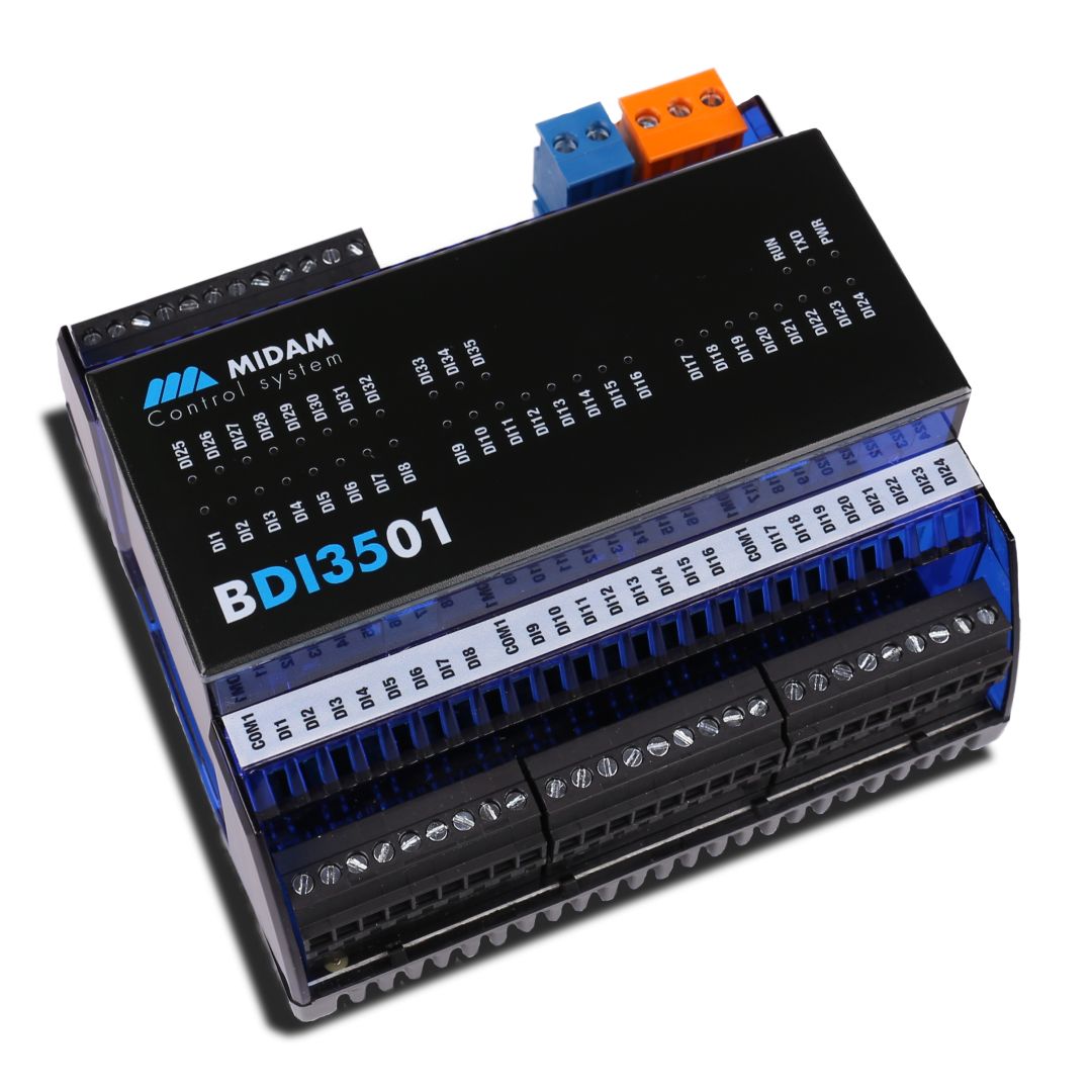
35 digital/counter inputs module - MIDAM BDI3501
Microprocessor controlled module featuring 35 binary (digital)/counter inputs. The serial line communication is based on Modbus RTU (RS485) protocol. Native modbus map grants seamless integration into variety of PLC/SCADA systems.
- Microprocessor-controlled module
- Modbus RTU (RS485)
- Native Modbus map
- Integration into PLC / SCADA systems
Function
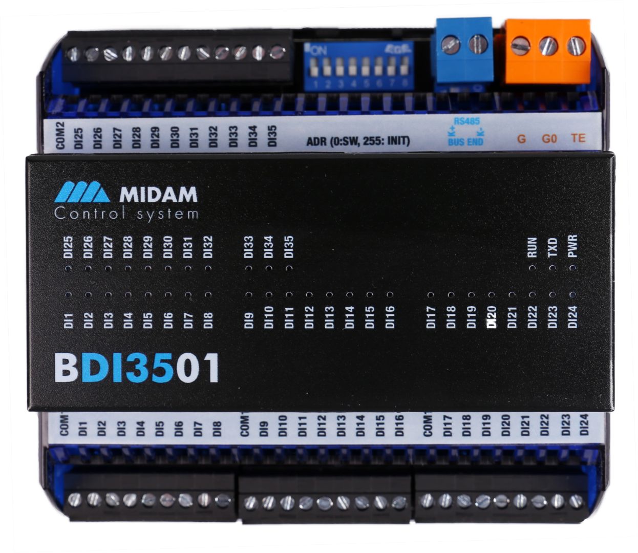
The BDI3501 module monitors up to 35 digital/counter inputs. All digital inputs are configurable and designed for small voltage up to 30 V DC, 26 V AC. Inputs DI1 to DI24 have common ground – COM1. Inputs DI25 to DI35 have common ground – COM2. The COMx terminals are not interconnected inside of the module. As a consequence, each of them may host different potential. The inputs are optically separated from the rest of the module power circuit. Please bear in mind there is no battery backup for the stored values in case of counting pulses acquisition. The device has factory-set values to ensure the correct default function and allows direct reading and writing of values to the Modbus map, which is available in a separate document. All settings are also stored in the Modbus map directly in the device. If the module is terminating the communication bus, i.e. it is the last in line, a terminating 120 R resistor may be switched on by short-circuiting of the BUS END DIP switch. Three LEDs located inside of the housing enable fast diagnostics like power, communication and system circle indication. The communication circuits are protected against overvoltage and galvanically isolated from other parts of the module. 35 LEDs indicate the status of each of the input separately. The module is equipped with a watchdog. The module features removable connectors available for all signals as well as for data and power line. This makes its installation and maintenance fast and easy. The module has a DIN rail clip (snap on).
Addressing
The Modbus address can be set in two ways. Using DIP switches, they increase their bit weight from right to left, see image with example where address of 98 is set by activation of switches 2, 3, and 7 with bit weight of 64, 32, and 2 respectively. Valid settable range is 1 to 254. Address 0 (all switches OFF) means that the address is set as entered in the Modbus table. Address 255 (all switches ON) brings the module to INIT (factory settings) mode, where Modbus address is 1 and communication parameters are set to 9600/8/N/1. Software addressing is available using appropriate software tool delivered by the device manufacturer. The software addressing feature is active provided the hardware addressing switch is set to 0 only. All changes apply after the module is switched off and on again.
Configuration
The device is configured using the manufacturer’s tool or with a standard modbus tool, modifying the appropriate registers. The different operation modes and user access can be configured in this way. Modifications to the controller configuration can be made afterwards without the need for any special tools.
PLC system integration
The module can be integrated via the Modbus RTU (RS485).